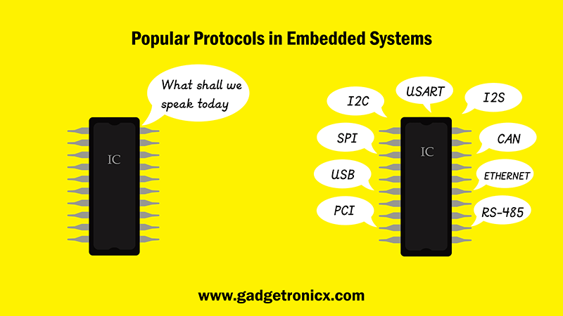
This physical layer IC circuitry is pretty standard and if you follow the design rules and circuit examples in the applications notes, your circuitry has a high probability of working correctly. However, we would typically have a standard IC of some flavor that would handle the translation of the physical layer communications protocol to something that the rest of the system can then deal with. Shouldn’t we discuss these as well?įair point. In fact, I have a laser printer in my office that came with USB and Ethernet already installed. You might argue that these protocols are pretty fundamental. Furthermore, we can also eliminate USB and Ethernet protocols from our discussion. Therefore, let’s narrow our scope to the types of communications systems that we would most likely have to deal with in designing real-time control systems without the necessity of resorting to specialized tools. Any discussion we might have about debugging these systems would quickly focus on what company’s analyzer one should purchase. They require highly specialized measurement tools to analyze and correct errors in the data streams. These systems are high-speed and complex.
List of serial communication protocol serial#
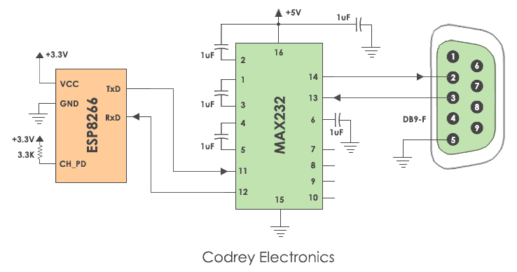
Today, serial communications protocols have greatly evolved and are being used both for peripheral communications as well as communications between elements of networks. Debugging the serial communications link was the first piece of I/O that the engineer needed to get working properly because communications with the target system depended upon this link working properly. Debugging typically involved getting the baud rates to properly match or messing around with transmitted data out and transmitted data in on pins 2 and 3 of the connector. Surprisingly, this is still true today because RS-232C is the most basic and fundamental of the serial communications protocols and is generally rather bulletproof. Berger PhD, in Debugging Embedded and Real-Time Systems, 2020 Introductionįor many years, debugging serial communications issues in embedded systems generally boiled down to debugging the vagaries of the RS-232 protocol. This action corresponds to the data link layer in the OSI model.Īrnold S.

If a transmitting node does not receive an acknowledgment for a data frame, it should retransmit the data frame until the data are acknowledged. The CRC field can be used to check a message's data field for correctness. The node can delay the transmission of the next frame with up to two overload frames in a row, hopefully giving it enough time to recover from its overload. An overload frame signals that a node is overloaded and will not be able to handle the next message. The bus also supports an overload frame, which is a special error frame sent during the interframe quiescent period. The error delimiter field allows the bus to return to the quiescent state so that data frame transmission can resume. Upon detecting an error, a node interrupts the current transmission with an error frame, which consists of an error flag field followed by an error delimiter field of 8 recessive bits. The ACK slot is followed by a single-bit delimiter followed by the end-of-frame field.Īn error frame can be generated by any node that detects an error on the bus. If the sender sees a 0 on the bus in the ACK slot, it knows that it must retransmit. The acknowledge field is used to let the identifier signal whether the frame was correctly received: the sender puts a recessive bit (1) in the ACK slot of the acknowledge field if the receiver detected an error, it forces the value to a dominant (0) value. A cyclic redundancy check (CRC) is sent after the data field for error detection. The data field is from 0 to 64 bytes, depending on the value given in the control field.


The control field provides an identifier extension and a 4-bit length for the data field with a 1 in between. When RTR = 1, the packet is used to write data to the destination identifier. The trailing remote transmission request (RTR) bit is set to 0 if the data frame is used to request data from the device specified by the identifier. The destination identifier is 11 bits long. (There are at least three bit fields between data frames.) The first field in the packet contains the packet's destination address and is known as the arbitration field. A data frame starts with a 1 and ends with a string of seven zeroes. The format of a CAN data frame is shown in Fig. 9.3.


 0 kommentar(er)
